
LED strip lighting can produce clean, continuous illumination for coves, shelves, ceilings, joinery, displays, stairs, and architectural details. A reliable installation, however, depends on more than selecting the strip itself. The system voltage, watts per metre, total run length, driver capacity, cable distance, controller limits, profile, heat management, and power-injection method all affect brightness consistency, efficiency, and service life. This guide explains how to plan a 12V, 24V, or 48V constant-voltage LED strip system, from the initial load calculation through driver selection, cable sizing, voltage-drop control, and final installation planning.
In This Guide
- How an LED Strip Lighting System Works
Understand the role of the strip, driver, controller, cable, profile, and power-injection points. - 12V vs 24V vs 48V LED Strips
Compare system current, cable losses, run length, compatibility, and typical applications. - How to Calculate LED Strip Power
Calculate total wattage from watts per metre and total strip length. - How to Size the LED Driver
Select adequate driver capacity without consistently operating the power supply near its maximum rating. - One Long Run vs Multiple Parallel Runs
Learn when dividing the installation improves voltage consistency, control, and maintenance. - LED Strip Voltage Drop Explained
Understand how voltage, current, cable length, and conductor size affect the voltage reaching the strip. - How to Choose the Cable Size
Use current and complete-route voltage drop to establish a preliminary copper-conductor size. - Maximum LED Strip Run Length
Understand why the manufacturer’s maximum feed length cannot be determined from watts alone. - Power Injection and Feed Methods
Compare one-end feeding, both-end feeding, centre feeding, multiple injection points, and distributed drivers. - Controllers, Dimmers, and Channel Limits
Check whether the controller, dimmer, amplifier, terminals, and wiring can carry the required current. - Aluminum Profiles and Heat Management
Select suitable profiles and diffusers to support cooling, protection, appearance, and light quality. - Common LED Strip Installation Mistakes
Avoid mismatched voltages, undersized drivers, long unsupported runs, excessive voltage drop, and inaccessible power supplies. - LED Strip Design Checklist
Review the complete system before ordering products or beginning installation.
How an LED Strip Lighting System Works
A LED strip installation is a complete low-voltage lighting system, not simply a strip connected to electricity. A typical system combines an AC supply, a constant-voltage LED driver, optional controls, low-voltage cabling, the LED strip, and an aluminum profile.
For placement ideas before sizing the electrical components, see under-cabinet kitchen lighting, bedroom and wardrobe lighting and corridor and stair lighting. This guide covers the strip, driver, control and cable design.
Each component must be compatible with the others. The driver voltage must match the strip, the driver and controller must carry the required load, and the cables must deliver power without excessive voltage drop.
The Basic Power Flow
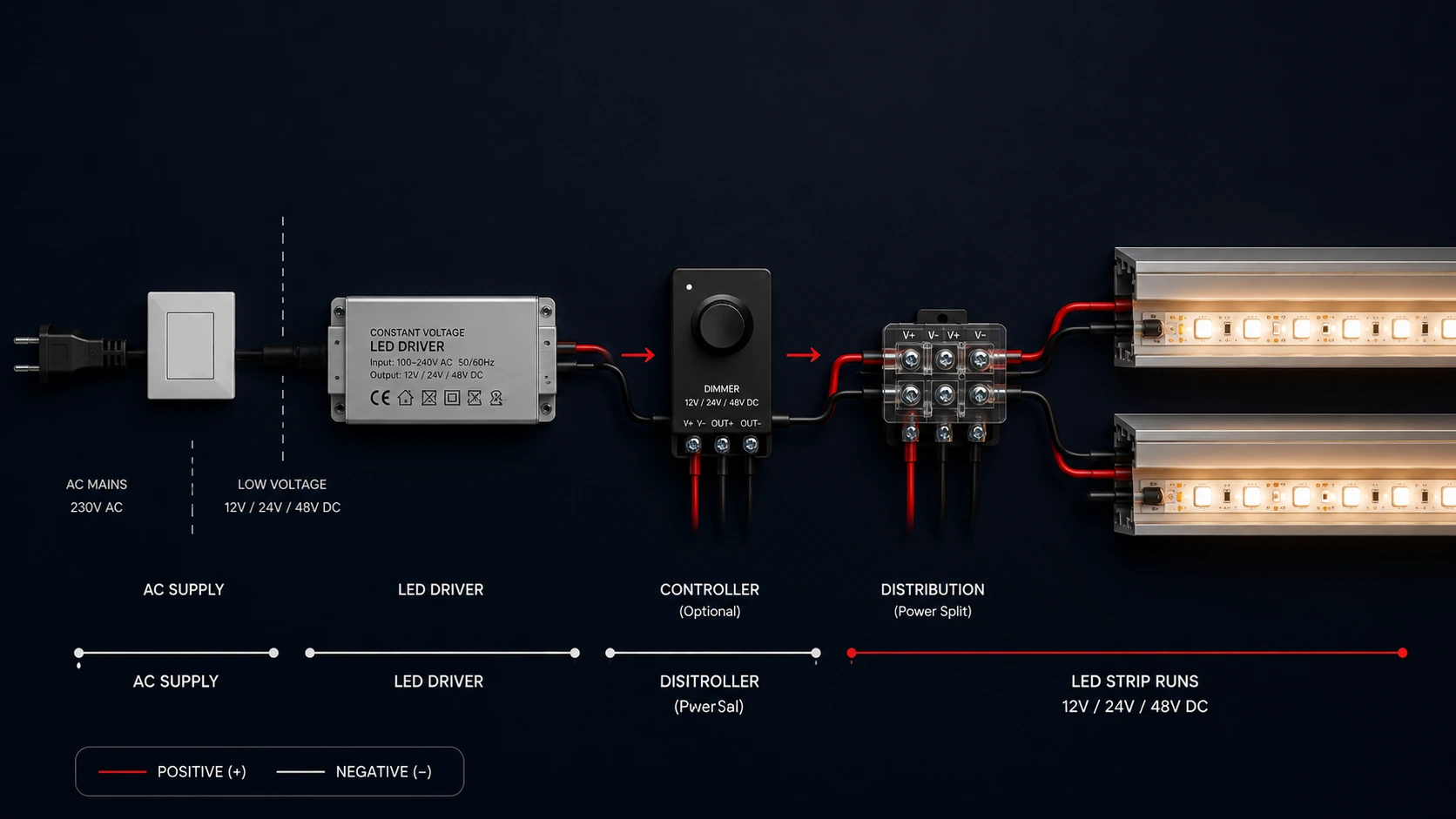
A distribution point may be added when one driver supplies several strip runs or power-injection points.
Main System Components
| Component | Purpose | Main Check |
|---|---|---|
| AC supply | Provides mains electricity | Supply voltage, switching, and protection |
| LED driver | Converts AC power to 12V, 24V, or 48V DC | Correct output voltage and adequate capacity |
| Controller or dimmer | Controls brightness, colour temperature, or colour | Voltage, channel type, and current limit |
| Low-voltage cable | Carries power to the strip | Distance, current, conductor size, and voltage drop |
| Distribution point | Divides power between multiple runs | Combined current, polarity, and terminal rating |
| LED strip | Produces the light | Voltage, W/m, lm/m, CRI, CCT, IP rating, and maximum run length |
| Aluminum profile | Supports and protects the strip | Strip width, profile depth, diffuser, and heat management |
- The Most Important Compatibility Rule
A constant-voltage LED strip must use a driver with the same output voltage:
- 12V strip → 12V constant-voltage driver
- 24V strip → 24V constant-voltage driver
- 48V strip → 48V constant-voltage driver
- Total current
- Number of strip runs
- Driver-to-strip distance
- Permitted voltage drop
The driver must also provide enough rated capacity for the complete strip load. Controllers, dimmers, connectors, and cables must be checked according to the current they will carry, not only the total wattage.
Practical Example
A 24V installation contains 10 metres of LED strip rated at 14.4W per metre.
Total connected load
14.4W/m × 10m = 144W
Using an 80% maximum driver-utilization target:
144W ÷ 0.80 = 180W minimum rated capacity
The installation therefore needs at least 180W of combined 24V constant-voltage driver capacity.
The final cable sizes will depend on:
12V vs 24V vs 48V LED Strips
The operating voltage of an LED strip directly affects current, cable losses, practical run length, and driver selection. For the same wattage, a higher-voltage system draws less current, which usually makes long runs easier to manage.
Why Voltage Matters
Electrical current is calculated as:
Current = Power ÷ Voltage
For the same 144W lighting load:
| System Voltage | Current Draw |
|---|---|
| 12V | 12A |
| 24V | 6A |
| 48V | 3A |
This is why 24V and 48V systems generally perform better over longer cable routes. Lower current reduces voltage drop, cable heating, and the burden placed on connectors, dimmers, and controllers.
Voltage Comparison
| Factor | 12V LED Strip | 24V LED Strip | 48V LED Strip |
|---|---|---|---|
| Current for the same wattage | Highest | Medium | Lowest |
| Voltage-drop sensitivity | Highest | Lower | Lowest |
| Typical project scale | Short decorative runs | Most residential and commercial projects | Long architectural runs |
| Cable-size requirement | Usually larger | More manageable | Often smaller for the same load |
| Power-injection frequency | More frequent | Moderate | Less frequent |
| Product availability | Common | Very common | More specialized |
| Typical use | Furniture, vehicles, small details | Coves, ceilings, shelves, profiles | Long linear systems and large projects |
When to Use 12V
A 12V strip can be suitable for:
- Short furniture or display details
- Small shelves and cabinets
- Battery or vehicle-related applications
- Projects where 12V equipment is already installed
- Installations requiring short cutting intervals, depending on the strip design
Its main limitation is current. A high-output 12V strip can draw significant current even over a relatively short installation, increasing cable-size and power-injection requirements.
When to Use 24V
For most architectural LED strip projects, 24V provides the best balance between availability, efficiency, control compatibility, and practical run length.
It is commonly used for:
- Ceiling coves
- Recessed profiles
- Shelving and joinery
- Retail displays
- Kitchens and wardrobes
- Residential and commercial ambient lighting
Compared with a 12V system of the same wattage, a 24V system draws half the current. This makes it easier to manage cable losses and distribute power across several runs.
When to Use 48V
A 48V system is particularly useful where the project includes longer runs, greater cable distances, or higher connected loads.
Typical applications include:
- Long architectural profiles
- Large commercial spaces
- Continuous linear lighting
- Projects with remotely located drivers
- Installations where reduced cable current is important
The main considerations are product availability and compatibility. The strip, driver, controller, connectors, and accessories must all support 48V operation.
Example: The Same Load at Three Voltages
Consider a 10-metre LED strip installation rated at 14.4W per metre:
14.4W/m × 10m = 144W total load
The resulting current would be:
- 12V: 144W ÷ 12V = 12A
- 24V: 144W ÷ 24V = 6A
- 48V: 144W ÷ 48V = 3A
The light output may be similar, but the electrical demands are very different. At 12V, the cable, controller, connectors, and distribution terminals must carry four times the current of the equivalent 48V system.
Practical Selection Rule
Choose the voltage according to the complete system, not the strip alone.
- Use 12V for short, compact installations where 12V is required.
- Use 24V as the default choice for most residential and commercial LED strip projects.
- Use 48V for longer runs, higher loads, or projects where reducing current and voltage drop is a priority.
Design note: Higher voltage does not remove the need to check maximum strip run length. The strip manufacturer’s feed limit still depends on PCB design, copper weight, LED density, and wattage per metre.
How to Calculate LED Strip Power
Before selecting a driver, controller, or cable size, calculate the total connected load of the LED strip installation.
The basic formula is:
Total Power = Strip Wattage per Metre × Total Strip Length
Example
A project uses:
- LED strip rating: 14.4W/m
- Total strip length: 10m
14.4W/m × 10m = 144W total connected load
This 144W figure is the electrical load of the strip only. It is the starting point for driver sizing, current calculation, cable selection, and controller checks.
Multiple Strip Runs
When the installation contains several runs, calculate each run separately, then add them together.
| Run | Length | Strip Rating | Connected Load |
|---|---|---|---|
| Run 1 | 5m | 14.4W/m | 72W |
| Run 2 | 3m | 14.4W/m | 43.2W |
| Run 3 | 2m | 14.4W/m | 28.8W |
| Total | 10m | — | 144W |
This approach is useful because each branch may later require a different cable size, feed method, or controller channel.
Mixed Strip Types
If a project uses strips with different wattages, calculate them individually.
Example:
| Strip Type | Length | Wattage | Load |
|---|---|---|---|
| Cove strip | 8m | 14.4W/m | 115.2W |
| Shelf strip | 4m | 9.6W/m | 38.4W |
| Feature strip | 3m | 19.2W/m | 57.6W |
| Total Connected Load | — | — | 211.2W |
The total connected load is therefore 211.2W.
Do Not Add Driver Margin Yet
At this stage, calculate the actual strip load only.
Do not include the driver safety margin inside the strip wattage calculation. The margin is applied afterward when selecting the driver.
For example:
- Actual strip load: 144W
- Driver capacity required at 80% utilization: 144W ÷ 0.80 = 180W
Keeping these two figures separate makes the design easier to review:
- Connected load: what the LED strips consume
- Required driver capacity: the minimum rated capacity selected for the system
Common Calculation Mistakes
Avoid:
- Using the strip reel length instead of the installed length
- Combining strips with different W/m ratings into one calculation
- Forgetting short sections inside shelves, cabinets, or returns
- Using nominal driver wattage as the strip load
- Adding the driver margin twice
- Ignoring separate zones connected to the same power supply
Practical Design Rule
Create a simple load schedule for every project showing:
- Strip reference
- Voltage
- Wattage per metre
- Length per run
- Load per run
- Total connected load
- Driver or controller assignment
This becomes the basis for the full electrical design and helps prevent under-sized drivers or overloaded control channels.
How to Size the LED Driver
Once the total connected load is known, the next step is selecting a constant-voltage driver with enough capacity to operate the installation reliably.
The driver should not normally be selected at exactly the same wattage as the strip load. A planning margin allows for heat, operating conditions, manufacturing tolerances, and future small adjustments.
Driver Sizing Formula
Required Driver Capacity = Total Strip Load ÷ Maximum Driver Utilization
For most projects, an 80% utilization target is a practical planning basis.
Example
A system has a total connected strip load of 144W.
144W ÷ 0.80 = 180W minimum driver capacity
The selected solution must therefore provide at least 180W of rated 24V output capacity.
Common Driver Arrangements
The required capacity may be provided by:
- One driver
- Two or more smaller drivers
- Separate drivers for different zones
- One driver per strip run
- One driver per controller or dimming circuit
The best arrangement depends on accessibility, zoning, cable distances, control requirements, and maintenance.
One Large Driver or Several Smaller Drivers?
| Arrangement | Advantages | Considerations |
|---|---|---|
| One large driver | Fewer components and simpler central maintenance | Higher branch current and longer low-voltage cable routes |
| Several smaller drivers | Shorter cable routes and easier zoning | More components and more access points |
| One driver per run | Clear load separation and easier troubleshooting | Higher installation cost |
| One driver per controlled zone | Simplifies dimming and automation | Requires coordinated driver and controller selection |
For large or distributed projects, several smaller drivers are often more practical than one central high-capacity unit.
A higher-wattage driver is acceptable when the voltage is correct. A different-voltage driver is not.
Check More Than Wattage
Before final selection, confirm:
- Output voltage
- Rated wattage
- Maximum output current
- Dimming method
- Input voltage
- IP rating
- Operating temperature
- Installation location
- Ventilation
- Access for replacement
- Compatibility with the controller or dimmer
Driver Current
The driver’s output current can be checked using:
Current = Power ÷ Voltage
For a 180W driver:
| Driver Voltage | Maximum Rated Current |
|---|---|
| 12V | 15A |
| 24V | 7.5A |
| 48V | 3.75A |
This current must also be considered when selecting terminals, connectors, controllers, and branch cables.
Avoid Oversizing Without Reason
A driver with a higher wattage rating does not force extra power into the strip. The strip draws the power it requires.
However, excessive oversizing may:
- Increase cost
- Increase physical size
- Complicate installation
- Reduce efficiency at very low load levels
- Make future troubleshooting less clear
The objective is not to select the largest driver available, but the smallest suitable arrangement that provides adequate capacity and reliable operation.
Practical Selection Example
A project has three strip runs:
| Run | Connected Load |
|---|---|
| Run 1 | 72W |
| Run 2 | 43.2W |
| Run 3 | 28.8W |
| Total | 144W |
Possible driver arrangements include:
- One 200W driver supplying all three runs
- Two 100W drivers divided by zone
- One driver per run, sized individually
- Separate drivers for dimmed and non-dimmed circuits
The final choice should reflect the actual cable routes and control layout, not wattage alone.
One Long Run vs Multiple Parallel Runs
A long LED strip should not automatically be treated as one continuous electrical run. In many projects, dividing the installation into shorter parallel runs gives better brightness consistency, lower voltage drop, and easier maintenance.
One Long Run
A single long run may be acceptable when:
- The strip length remains within the manufacturer’s feed limit
- The wattage per metre is moderate
- The cable route is short
- Brightness loss at the far end is acceptable
The main risk is progressive voltage loss along the strip, which can cause the far end to appear dimmer.
Multiple Parallel Runs
Parallel runs are usually better when:
- The total installation is long
- The strip has a high wattage per metre
- Several coves, shelves, or profiles are supplied from one location
- Consistent brightness is important
- Separate zoning or maintenance access is required
Each run receives its own feed from the driver, controller, or distribution point.
Comparison
| Layout | Best For | Main Consideration |
|---|---|---|
| One continuous run | Short, simple installations | Must remain within the strip feed limit |
| Two equal parallel runs | Medium-length coves or profiles | Requires a proper distribution point |
| Several parallel runs | Large or divided installations | Each branch must be sized separately |
| Separate driver per run | Long or independently controlled zones | Higher component cost |
Practical Example
Instead of powering one 10m strip from one end, divide it into two 5m runs supplied in parallel.
This can improve:
- Brightness consistency
- Voltage-drop control
- Cable organization
- Troubleshooting
- Future replacement
Design Rule
Do not choose the run arrangement based only on total wattage. Also consider:
- Maximum strip feed length
- Cable distance
- Current per branch
- Controller limits
- Access to drivers and junction points
LED Strip Voltage Drop Explained
Voltage drop is the gradual loss of voltage as power travels through the cable and along the LED strip.
The result is easy to spot:
- The beginning looks bright
- The far end looks weaker
- Colours may shift
- Long runs may feel inconsistent
What Causes It?
Voltage drop increases when:
- Cable distance is longer
- Current is higher
- Cable size is smaller
- The system voltage is lower
That is why the same load is harder to manage at 12V than at 24V or 48V.
Quick Rule
Longer distance + higher current = more voltage drop
Simple Example
A 144W load draws:
- 12A at 12V
- 6A at 24V
- 3A at 48V
Lower current means less cable loss and more consistent brightness.
How to Reduce It
Use one or more of these:
- Increase cable size
- Shorten the cable route
- Divide the installation into parallel runs
- Use power injection
- Move the driver closer
- Select a higher system voltage
A good LED strip design should look equally bright from beginning to end.
How to Choose the Right Cable Size
Cable size affects how much voltage reaches the LED strip.
Too small, and you may get:
- Dimmer light at the far end
- Colour inconsistency
- Warm cables or connectors
- Unstable performance
What Determines Cable Size?
Focus on four things:
| Factor | Effect |
|---|---|
| Current | More current needs a larger conductor |
| Distance | Longer runs increase voltage loss |
| System voltage | 12V is more sensitive than 24V or 48V |
| Allowed voltage drop | Tighter limits may require thicker cable |
Simple Rule
Higher current + longer distance = larger cable
Important Detail
Measure the full circuit path:
Driver to strip + return path
For a 10m one-way cable route, the calculation uses a 20m conductor loop.
Good Practice
- Size the main cable for the combined load
- Size each branch for its own current
- Keep cable routes as short as practical
- Check terminal capacity before increasing cable size
- Use copper conductors with secure connections
Quick Design Tip
A larger cable can reduce voltage drop, but it does not solve voltage loss inside a long LED strip. Long runs may still need shorter sections or power injection.
Maximum LED Strip Run Length
Every LED strip has a practical limit for how far it should be powered from one feed.
Push beyond it, and the far end may become:
- Dimmer
- Warmer in colour
- Less stable
- Visibly uneven
What Sets the Limit?
Maximum run length depends on:
- Strip voltage
- Wattage per metre
- PCB width and copper weight
- LED density
- Internal strip resistance
- Manufacturer design
This means two strips with the same wattage can still have different maximum run lengths.
Important Rule
Do not estimate maximum run length from wattage alone.
Always check the product datasheet or manufacturer specification.
When the Run Is Too Long
Use a better feed arrangement:
- Split it into shorter parallel runs
- Feed from both ends
- Feed from the centre
- Add power-injection points
- Use separate drivers
Quick Example
Instead of one 12m strip fed from one end:
Better: two 6m runs fed in parallel.
Power Injection and Feed Methods
Power injection sends power to more than one point along the LED strip. It helps keep brightness consistent and reduces the current carried through one long strip section.
Common Feed Methods
| Method | Best Use |
|---|---|
| One-end feed | Short runs within the manufacturer limit |
| Both-end feed | Medium runs needing better brightness consistency |
| Centre feed | Two equal sections extending from one central point |
| Multiple injection points | Long or high-power installations |
| Parallel runs | Several shorter strips supplied separately |
Quick Visual
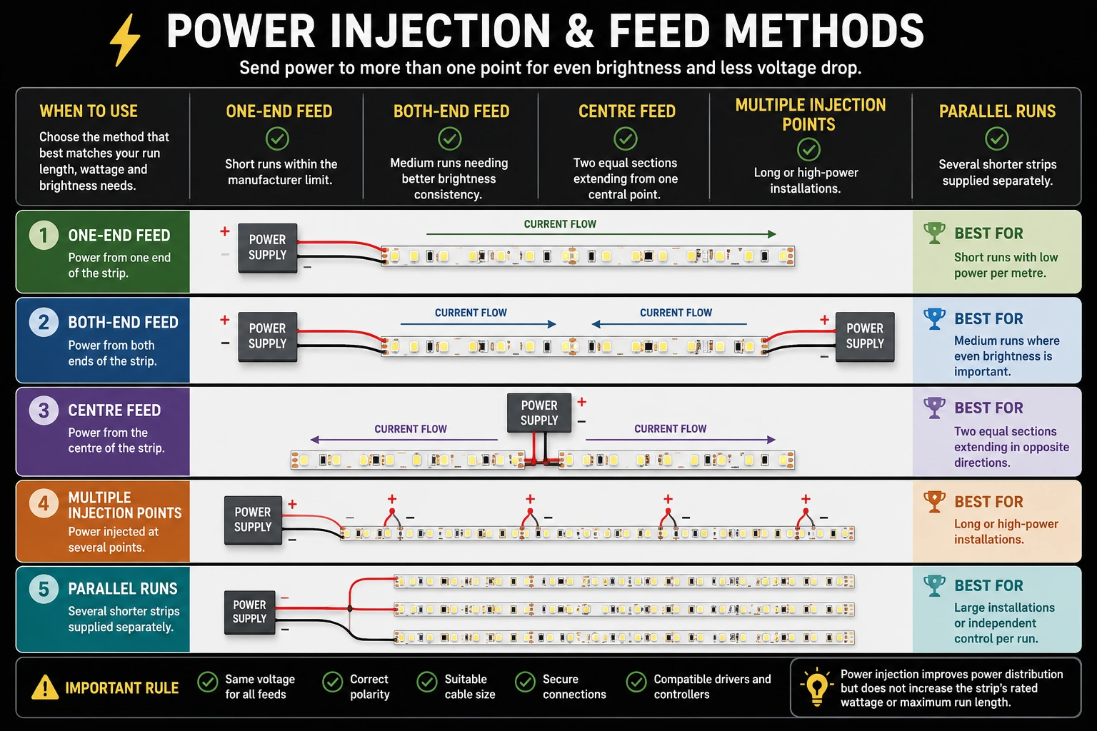
Important Rule
All feeds must use:
- The same voltage
- Correct polarity
- Suitable cable sizes
- Compatible drivers and controllers
Power injection improves distribution, but it does not increase the strip’s rated wattage or remove the manufacturer’s maximum-run restrictions.
Best Practical Choice
For many projects, the cleanest approach is to divide one long installation into several shorter parallel runs. It is usually easier to calculate, maintain, and control.
Do not connect the outputs of separate drivers to the same continuous electrical section of LED strip unless the driver manufacturer explicitly permits parallel operation. When using multiple drivers, divide the strip into electrically isolated sections.
Controllers, Dimmers and Channel Limits
Controllers and dimmers sit between the driver and the LED strip, so they must be able to carry the actual current of the connected load.
Match the Controller to the Strip Type
| Strip Type | Typical Controller |
|---|---|
| Single colour | 1-channel dimmer |
| Tunable white | 2-channel CCT controller |
| RGB | 3-channel RGB controller |
| RGBW | 4-channel RGBW controller |
Check Current per Channel
Do not judge a controller only by total wattage.
A controller rated 4 × 5A can carry up to 5A on each channel. One overloaded channel can fail even when the total load appears acceptable.
Quick Example
A 24V single-colour strip load of 120W draws:
120W ÷ 24V = 5A
The dimmer must therefore support at least 5A on that channel, with a sensible operating margin.
Key Checks
- Correct system voltage
- Correct number of channels
- Current limit per channel
- Total controller capacity
- Compatible dimming method
- Suitable terminals and cable size
- Accessible installation location
Design Tip
For large loads, divide the installation across several controller channels, amplifiers, or separate zones instead of pushing one channel close to its maximum.
Aluminum Profiles and Heat Management
An aluminum profile is not only decorative. It supports the strip, improves alignment, protects the LEDs, and helps move heat away from the PCB.
Why Profiles Matter
A suitable profile can improve:
- Heat dissipation
- Strip lifespan
- Diffusion and visual comfort
- Protection from dust and contact
- Installation quality
- Future maintenance
Match the Profile to the Application
| Application | Suitable Profile |
|---|---|
| Ceiling cove | Recessed or surface profile |
| Shelf or cabinet | Slim furniture profile |
| Corner lighting | 45° corner profile |
| Continuous line of light | Deep profile with diffuser |
| Architectural detail | Trimless or recessed profile |
Check Before Installation
Confirm:
- The strip fits inside the channel
- The diffuser depth gives the desired light effect
- The profile can dissipate the strip’s heat
- Connectors and cables have enough space
- The profile remains accessible where maintenance is required
Quick Tip
High-output strips should not be installed inside undersized profiles or directly onto heat-sensitive surfaces.
A deeper profile may also reduce visible LED dots and create a cleaner, more continuous line of light.
Common LED Strip Installation Mistakes
Most LED strip problems come from small design errors rather than the strip itself.
Avoid These Common Mistakes
| Mistake | Result |
|---|---|
| Wrong driver voltage | Strip failure or incorrect operation |
| Driver sized too close to the load | Overheating and reduced reliability |
| Cable too small | Voltage drop and dimmer light |
| One long unsupported run | Uneven brightness |
| Controller channel overloaded | Unstable dimming or controller damage |
| Poor polarity control | Sections fail to light |
| No aluminum profile | Higher heat and weaker finish quality |
| Hidden inaccessible drivers | Difficult maintenance and replacement |
Fast Design Check
Before installation, confirm:
- Voltage matches across all components
- Driver capacity includes a suitable margin
- Each branch current is calculated
- Cable size suits the distance
- Strip runs stay within feed limits
- Controllers can carry the assigned load
- Drivers and junctions remain accessible
Quick Tip
A clean installation starts with a clean layout. Mark the driver location, cable routes, strip lengths, and injection points before ordering the equipment.
LED Strip Design Checklist
Use this checklist before ordering products or starting installation.
System Selection
- Strip voltage confirmed: 12V, 24V, or 48V
- Strip wattage per metre confirmed
- Total installed length measured
- Maximum feed length checked
- Colour temperature, CRI, IP rating, and LED density confirmed
Power and Control
- Total connected load calculated
- Driver capacity includes a suitable margin
- Driver voltage matches the strip
- Controller type matches the strip
- Current per controller channel checked
- Dimming or automation method confirmed
Cable and Distribution
- Main cable sized for the combined load
- Branch cables sized individually
- One-way cable distances measured
- Voltage drop checked
- Distribution points remain accessible
- Polarity is clearly identified
Run Layout
- Long runs divided where necessary
- Power-injection points planned
- Parallel runs balanced
- Driver and controller locations coordinated
- Junctions and connections remain serviceable
Profiles and Installation
- Strip width fits the profile
- Profile depth suits the diffuser
- Heat dissipation is adequate
- Cable and connector space is available
- Mounting surface is clean and prepared
- Drivers have ventilation and maintenance access
Final Check
Before powering the system:
- Test voltage and polarity
- Inspect every connection
- Confirm all terminals are secure
- Test each zone separately
- Compare brightness from beginning to end
- Check dimming and control response
- Record driver, controller, and circuit assignments
A well-designed LED strip system should be easy to install, consistent in brightness, simple to maintain, and clear enough for another professional to understand later.
Final Takeaway
Successful LED strip lighting depends on the complete system, not one product. Strip voltage, total load, driver capacity, controller limits, cable size, run length, power injection, and heat management must all work together.
When these elements are planned correctly, the result is cleaner light, more consistent performance, and a more reliable installation.
Plan Your LED Strip System
Calculate your connected load, driver capacity, cable size, and estimated voltage drop before selecting the system components.
Browse LED strip lights once the voltage, output, installation conditions and control requirements are defined.