
Modular lighting systems offer more flexibility than a fixed arrangement of ceiling lights. Spotlights, linear modules, wall washers and pendants can be combined within one compatible system and repositioned as the room changes.
That flexibility depends on careful planning. The track or profile, lighting modules, connectors, power components, drivers and mounting accessories must work together as one system. A visually attractive track layout can still fail if it does not follow the furniture, lighting tasks or electrical limits.
This guide explains how to plan modular and magnetic track lighting from the room layout through installation and commissioning—without turning the process into a complicated component exercise.
In This Guide
What modular lighting systems include
Magnetic, conventional and belt system differences
How to plan from the room layout
Surface-mounted, recessed and suspended installation
Track runs, corners, joins and power entry
Drivers, connected load and capacity reserve
Circuits and control zones
Spotlight, linear, pendant and wall-washing modules
Beam angles, spacing and aiming
System compatibility
Future flexibility
Ceiling coordination
Installation and commissioning
A final planning checklist
1. What Is a Modular Lighting System?
A modular lighting system combines a supporting track, profile or belt with compatible lighting modules and electrical components.
If you are still choosing between systems, start with magnetic track lighting vs recessed spotlights. This guide takes the next step: planning a complete compatible system.
Depending on the selected family, the available modules may include:
Adjustable spotlights
Fixed or directional floodlights
Linear lighting modules
Wall-washing modules
Suspended pendants
Decorative modules
Direct and indirect lighting elements
The individual modules can often be repositioned, replaced or added within the system’s permitted electrical and mechanical limits. This makes modular lighting useful where furniture, displays, artwork or room functions may change.
The key word is system. The track is only one part of the installation. Connectors, power feeds, drivers, mounting accessories and lighting modules must all belong to the same confirmed family or be explicitly approved for use together.
A modular installation should therefore be planned as one complete assembly—not as a collection of products selected independently.
2. Understand the Main System Types
Modular lighting is available in several formats. They can serve similar lighting purposes, but their components and electrical arrangements are not interchangeable.
Standard magnetic track systems
Standard magnetic systems use compatible modules that attach mechanically and electrically to a dedicated track. They can provide a broad choice of spotlights, linear modules and decorative elements.
Their larger physical format can make them suitable for substantial residential, retail and commercial interiors.
Mini magnetic track systems
Mini magnetic systems use a slimmer track and smaller modules. They can create a more delicate visual line in spaces where the lighting structure should remain discreet.
The reduced dimensions do not mean that components from different mini systems will work together. Each family still has its own track, connectors, modules and capacity limits.
Belt lighting systems
Belt systems use a flexible or tensioned supporting element rather than a conventional rigid track. They can introduce a more expressive architectural character and may suit spaces where the lighting system is intended to remain visibly present.
Their installation method, tensioning, power connection and module attachment differ from rigid track systems.
Conventional track lighting
Traditional two-wire and four-wire track systems commonly support adjustable track spotlights.
A basic two-wire arrangement normally operates as one switched group. A four-wire system can support more than one lighting circuit on the same physical track when the system and installation are configured accordingly.
Other modular profile systems
Some modular systems use recessed profiles, trimless channels, modular downlights or other family-specific structures. Their visual appearance and installation details can differ significantly even when they serve similar lighting functions.
Choose the system type according to the room, ceiling, required lighting effects and controls. Do not choose it by appearance alone.
3. Start With the Space, Not the Track
The lighting plan should begin with the room below the ceiling.
Before drawing any track lines, identify:
Room dimensions
Ceiling height and construction
Furniture positions
Main circulation paths
Work surfaces
Artwork and displays
Architectural features
Daylight direction
Fixed and flexible zones
Required control groups
A track line should provide useful lighting positions for the activities and surfaces beneath it. Installing a geometric track pattern first and trying to aim fixtures afterward can produce unnecessary modules, awkward beam angles and areas that remain poorly illuminated.
For example, a track in a living room may need to reach seating, artwork and a reading position. In a showroom, it may need to serve shelving and displays that change over time. In an office, it may need to support work areas without producing screen glare.
Estimate the required light level for each zone before choosing the number or type of modules. The Lux and Lumens Lighting Guide explains how illuminance and lumen requirements relate to the room. Preliminary quantities can also be explored with the Lux and Lumens Calculator.
4. Define the Lighting Layers
A modular system can support several lighting layers, but each module should have a defined purpose.
Ambient lighting
Ambient light provides the background illumination needed to understand and move through the room. Linear or wide-distribution modules can contribute to this layer.
Task lighting
Task lighting supports activities such as reading, working, cooking, preparing products or serving customers. It should be directed toward the task without producing uncomfortable shadows or glare.
Accent lighting
Accent lighting gives visual priority to artwork, merchandise, textures or architectural features. Adjustable spotlights are commonly used because their direction can be changed as the display develops.
Vertical lighting
Vertical illumination reaches walls, shelving and faces. It can make a space feel brighter without relying only on high horizontal illuminance at floor level.
Decorative lighting
Compatible pendant or decorative modules can create focal points above tables, counters or seating areas. Their visual role should be supported by the other lighting layers rather than expected to illuminate the entire room.
A single track may support several of these functions. The module selection and control plan should make those functions clear.
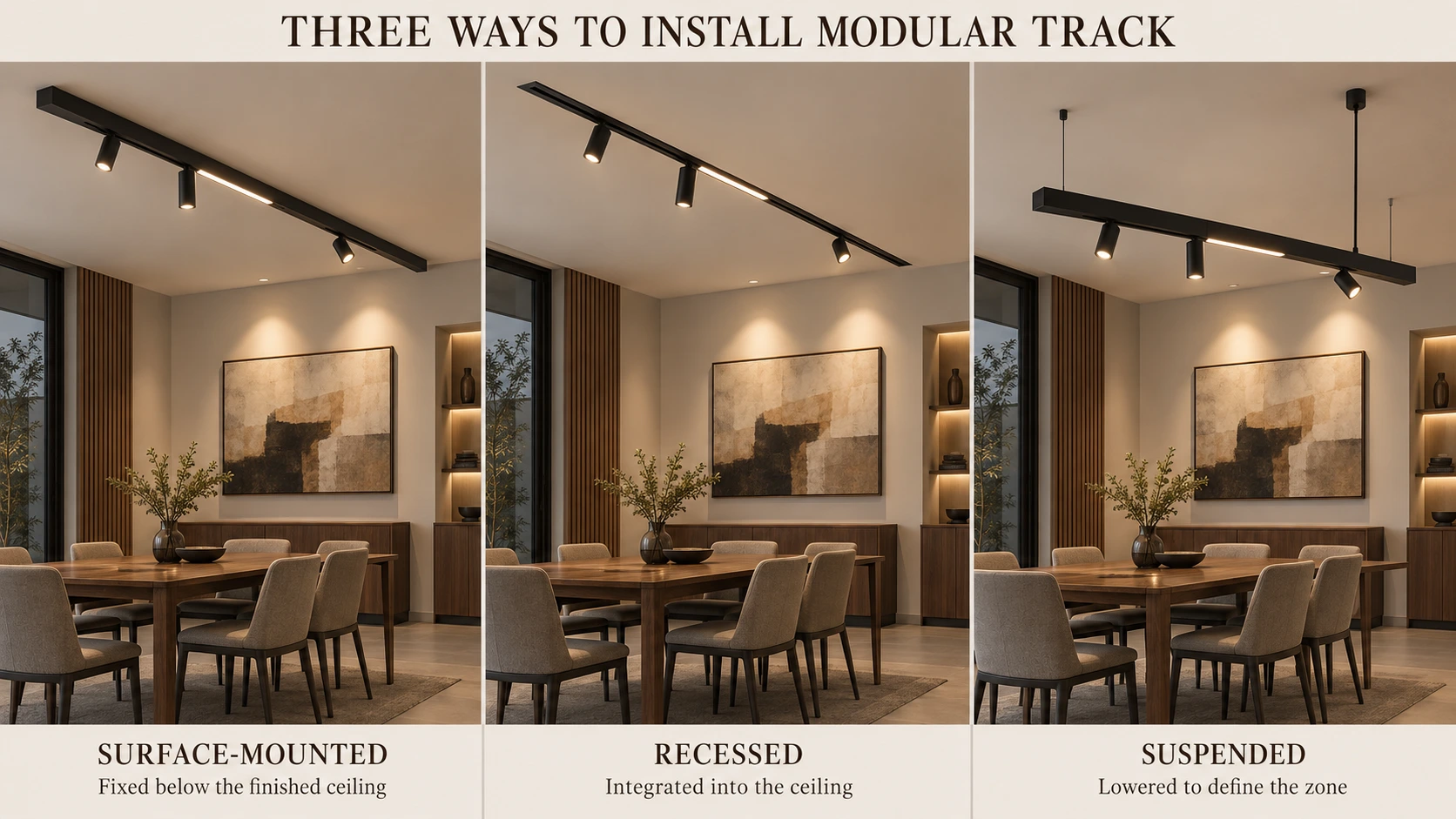
5. Choose Surface-Mounted, Recessed or Suspended Installation
The mounting method affects the appearance, ceiling coordination and future access to the system.
Surface-mounted installation
A surface-mounted track is fixed directly to the finished ceiling or another suitable structural surface.
It is useful when:
The ceiling is already complete
Recessing is not practical
Installation access is important
The track can remain visually visible
The project requires a relatively direct installation method
Surface mounting still requires coordinated power-entry points, straight alignment and suitable structural fixing.
Recessed installation
A recessed track is integrated into the ceiling so that all or part of its profile sits within the finished surface.
It is useful when:
A cleaner architectural appearance is required
Ceiling construction provides enough space
The profile, connectors and power entry can be coordinated early
The recess and finishing details can be completed accurately
Recessed and trimless systems should be planned before the ceiling is closed. Profile depth, plastering details, access and expansion at joins can affect the finished result.
Suspended installation
A suspended track is lowered from the ceiling using cables, rods or family-specific suspension components.
It is useful when:
The ceiling is high
Light must be brought closer to the working plane
The track is intended to define a table, counter or zone
Ceiling services make direct mounting difficult
The lighting system is part of the architectural expression
Suspension points must support the complete system and maintain alignment. The power feed should be coordinated with the suspension arrangement rather than added as an unrelated cable afterward.
6. Map the Track Runs and Geometry
After defining the lighting zones and mounting method, map the track runs.
Possible arrangements include:
One straight run
Parallel runs
L-shaped layouts
U-shaped layouts
Perimeter arrangements
Intersecting lines
Branched layouts
Separate runs for independent zones
The simplest layout that reaches the required lighting positions is usually the strongest starting point.
Check the track against:
Distance from walls
Furniture centres
Display and artwork locations
Curtain tracks
Cabinet and door movement
Air-conditioning diffusers
Sprinklers and detectors
Ceiling joints
Access panels
Projectors and speakers
A track positioned too close to a wall may create steep, uneven accent beams. A track placed directly above a glossy desk or dining position may create glare. A line that looks centred on an empty ceiling may become visually disconnected when the furniture is installed.
Allow adjustable modules enough distance to aim toward their targets without reaching the mechanical limit of their rotation.
7. Resolve Corners, Joins and Power Entry
A complete layout requires more than track lengths.
Depending on the selected system, it may also require:
Mechanical straight joins
Electrified straight connectors
Internal or external corners
Flexible corner connectors
T-connectors
Cross-connectors
Live connectors
Power-entry components
End caps
Recessing accessories
Suspension components
Mechanical continuity and electrical continuity are not always provided by the same component. Two profile sections may be physically joined while still requiring a separate electrical connection.
Every corner, branch and interrupted run should therefore be checked individually.
Power entry should also be planned before installation. Determine:
Where the electrical supply reaches the system
Whether power enters at an end or intermediate point
Whether the selected family allows the proposed feed position
Where the driver or power supply will be located
Whether the driver remains accessible
Whether separate zones need separate feeds
Do not assume that one power entry can serve every shape, branch or total run length. The permitted arrangement depends on the selected system and its electrical design.
8. Understand Drivers, Voltage and Capacity
Many modular lighting systems use a dedicated driver or power supply. Its purpose is to provide the voltage and current required by the compatible modules.
The selected driver must match:
System voltage
Combined connected wattage
Control and dimming method
Installation environment
Permitted wiring arrangement
Manufacturer requirements
Do not assume that every magnetic track system operates at the same voltage. Similar-looking systems may use different electrical architectures.
Calculate the connected load
Add the rated wattage of every module that will operate from the driver or power section.
As a practical planning rule, avoid loading a driver continuously to its maximum rating. Unless the selected manufacturer requires a larger allowance, approximately 20% unused capacity provides a sensible design reserve.
For example, modules with a combined connected load of 80W should not normally be assigned to an 80W driver. A higher compatible capacity allows for operating reserve and limited future additions.
Capacity must also be checked at the system level. A sufficiently large driver does not automatically mean that unlimited wattage can be connected to one track, connector or power feed.
Use the Modular Lighting Planner to plan the selected family, layout and compatible components. The planner should handle the exact component quantities and electrical sizing after the design intent has been established.
9. Divide the System Into Circuits and Control Zones
A continuous track does not necessarily need to behave as one lighting group.
Separate control zones can support:
General lighting
Task lighting
Accent lighting
Wall lighting
Displays
Window areas
Decorative pendants
Evening scenes
Independent room sections
A showroom may need to reduce general lighting while retaining display accents. A restaurant may use brighter settings during preparation and softer table-focused scenes during service. A home may require ambient and artwork lighting to operate independently.
The available control arrangement depends on the selected system.
A conventional four-wire track may allow more than one switched circuit on the same physical track. Other modular systems may require separate feeds, control-compatible drivers or dedicated control modules.
Confirm compatibility across:
Lighting modules
Drivers
Dimmers
Control equipment
Track circuits
Smart-control components
A product described as dimmable still needs a compatible driver and control method. Mismatched equipment can produce unstable low-level output, flicker, abrupt cut-off or inconsistent dimming between modules.
Plan the controls while planning the track—not after every component has been ordered.
10. Select Modules According to Their Function
Choose modules by the lighting effect they need to produce.
Adjustable spotlights
Adjustable spotlights are useful for:
Artwork
Displays
Tables
Architectural details
Directional task lighting
They provide flexibility, but every spotlight should have a target. Too many visible spotlights aimed without a clear purpose can make the installation feel cluttered.
Flood or wide-distribution modules
Wider-distribution modules can support:
Ambient illumination
Circulation
Broad working areas
Softer overlapping coverage
They are useful where a concentrated spotlight would create excessive contrast or leave noticeable dark gaps.
Linear modules
Linear modules can provide:
Continuous ambient light
Work-surface lighting
Soft circulation light
A quieter architectural appearance
Check the actual light distribution. A product that looks linear does not necessarily provide wide or uniform illumination.
Wall-washing modules
Wall-washing modules are designed to distribute light across vertical surfaces.
They can support:
Artwork arrangements
Textured walls
Shelving
Retail displays
Architectural surfaces
Their effectiveness depends on distance from the wall, beam distribution and mounting height.
Pendant modules
Compatible pendants can define:
Dining tables
Counters
Reception positions
Seating zones
Decorative focal points
Confirm suspension height, head clearance, table alignment and glare from seated positions.
Select the required lighting role first. Then choose a compatible module with the appropriate appearance, output and optical distribution.
11. Coordinate Beam Angles, Spacing and Aiming
Beam angle affects the diameter and concentration of light produced by a spotlight.
In general:
Narrow beams create concentrated emphasis
Medium beams provide adaptable accent lighting
Wide beams cover larger surfaces more softly
The visible result also depends on:
Mounting height
Distance to the target
Fixture output
Optical quality
Surface reflectance
Aiming angle
Overlap between adjacent beams
A narrow beam may suit a small object or high-contrast accent. It may be too concentrated for a large artwork or working surface. A wide beam may illuminate a broad area but spill beyond the intended target.
Use the Beam Angle Guide to understand the main optical differences. Preliminary coverage can be estimated with the Beam Angle Calculator.
Where several spotlights provide general or task lighting, the Spotlight Layout Calculator can help estimate spacing and quantity.
Calculator results provide a planning starting point. Final fixture selection and spacing should be checked using the selected product’s photometric data and actual mounting conditions.
12. Confirm Compatibility Before Ordering
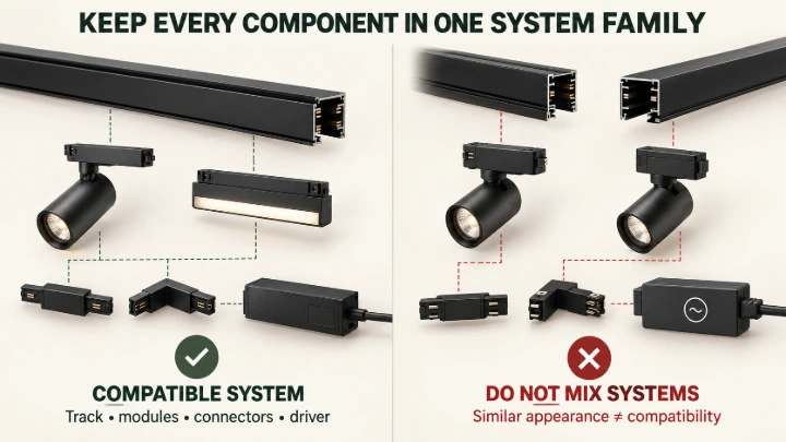
Compatibility is one of the most important parts of modular lighting planning.
Browse modular lighting systems and standard magnetic track systems as complete product families. Confirm every selected module and accessory belongs to the chosen compatible system.
Check compatibility across:
Track or profile
Lighting modules
Mechanical joins
Live connectors
Corners and branches
Power-entry components
Drivers
Voltage
Control method
Recessing accessories
Suspension accessories
End caps and finishing components
Similar dimensions do not confirm compatibility. Neither does magnetic attachment alone.
Components that look similar are not automatically electrically or mechanically compatible.
A module may attach to another family’s track but use different contacts, polarity, voltage, communication or locking details. An incorrect combination can remain unsecured, fail to operate or damage the system.
Select components from one confirmed family unless the manufacturer or supplier explicitly approves a cross-family combination.
When browsing products, use the stated System Compatibility information rather than comparing appearance alone. The Modular Lighting Planner should then be used to assemble supported family combinations and component requirements.
13. Plan for Future Changes
Adaptability is one of the main advantages of a modular system.
Future changes may include:
Moving furniture
Replacing artwork
Rearranging retail displays
Joining or separating tables
Adding a work position
Changing a room’s function
Replacing spotlight modules
Adding compatible linear or decorative elements
Useful flexibility comes from thoughtful track positioning and available capacity—not from filling every track with fixtures.
Plan for future changes by providing:
Track positions that can reach more than one arrangement
Accessible drivers and power feeds
Clearly documented circuits
Appropriate electrical reserve
Space for additional compatible modules
Module types that can be repositioned easily
Avoid installing unnecessary fixtures merely because the track has empty space. Excessive module quantities increase connected load, energy use and visual clutter.
Future additions must remain within the driver, feed, connector and track capacity. Available physical space does not confirm available electrical capacity.
14. Coordinate With the Ceiling and Building Services
Modular lighting should be coordinated with the ceiling structure and other services before installation begins.
Review the proposed layout against:
Structural support
Gypsum-board framing
Suspended-ceiling grids
Ceiling joints
Air-conditioning diffusers
Sprinklers
Smoke detectors
Speakers
Cameras
Access panels
Curtains
Joinery
Projection equipment
Maintenance routes
Recessed systems
Confirm:
Required profile depth
Ceiling opening dimensions
Framing and support
Plastering or trim detail
Connector access
Driver access
Finishing sequence
Surface-mounted systems
Confirm:
Fixing positions
Ceiling flatness
Visible cable entry
Alignment across joints
Connector and end-cap clearance
Suspended systems
Confirm:
Structural suspension points
Suspension spacing
Finished mounting height
Alignment between sections
Power-feed routing
Clearance from services and occupants
Late coordination can force the track away from its intended lighting position or leave drivers and connectors inaccessible. Resolve these conditions before closing the ceiling.
15. Install, Aim and Commission the Complete System
Installation is not complete when the track and modules are physically in position. The system must be tested, aimed and adjusted.
Commissioning should include:
Confirming the installed system family
Checking every mechanical join
Confirming electrical continuity
Verifying power-feed locations
Testing each circuit separately
Testing dimming and control behaviour
Confirming driver accessibility
Aiming adjustable modules
Checking wall and display coverage
Measuring important working surfaces
Checking glare from normal viewing positions
Recording the final module arrangement
Aim the fixtures after the furniture, displays and artwork are installed. Aiming toward temporary or estimated positions usually creates unnecessary rework.
Check the finished installation from seated, standing and circulation viewpoints. A source that appears shielded from one position may produce glare from another.
Also compare neighbouring modules for:
Colour consistency
Dimming consistency
Unexpected flicker
Beam uniformity
Visible brightness differences
The Light Quality Explained guide provides more detail about CRI, R9, SDCM, glare and flicker.
16. Final Modular Lighting Planning Checklist
Before ordering the system, confirm that:
The room layout is finalized
Lighting zones and visual tasks are defined
The required lighting layers are identified
The system family is selected
The mounting method suits the ceiling
Track runs follow useful lighting positions
Corners, joins and branches are resolved
Power-entry points are identified
Driver locations are accessible
Connected load and reserve are checked
Track and feed capacity are confirmed
Circuits and control groups are planned
Every module has a defined lighting role
Beam angles suit the mounting height and targets
All components have confirmed system compatibility
Ceiling services are coordinated
Future changes remain possible
Installation and commissioning responsibilities are clear
Bringing the System Together
A successful modular lighting installation begins with the room, not the product list.
Define the lighting zones and layers first. Then choose the system format, mounting method and track geometry. Resolve power, connectors and controls before selecting the final modules.
Keep every component within one confirmed compatible family, allow sensible electrical reserve and leave the driver and important connections accessible. After installation, aim and test the system with the completed furniture, artwork and displays in place.
When the planning decisions are clear, use the Modular Lighting Planner to organize the selected system, required components and electrical capacity.
For other lighting calculations and planning support, explore the complete collection of Saleh Deco Lighting Tools.